The DE10A pager

Pagers are widely used in emergency services. They serve a critical role and are highly specialized devices with an equally high price point. In this deep dive, we'll take a look at the DE10A pager hardware by Swissphone, and it's surrounding ecosystem.
What does a pager do?
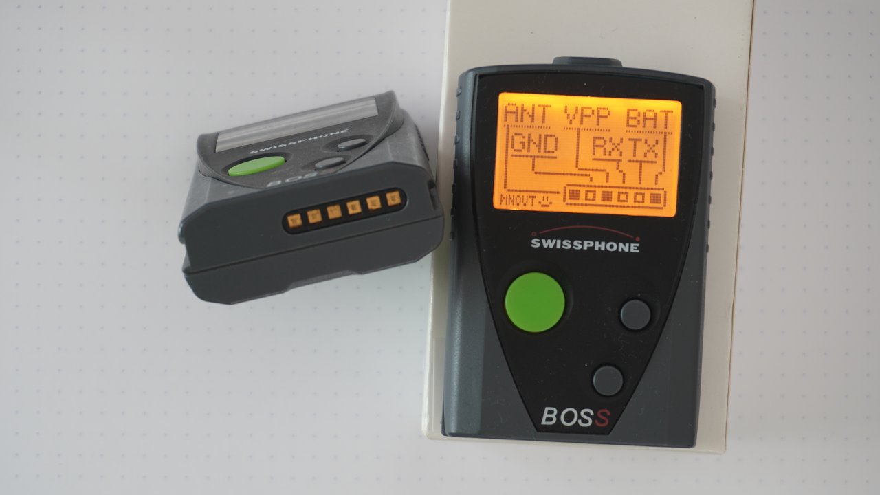
In general, pagers are simple devices. All they do is receive messages with certain IDs, called RICs (Radio Identification Codes). These messages can contain a small chunk of text. For emergency services they notify the user of an alarm; often with additional information such as location and type of emergency. There are a few different vendors for pager hardware. Among the most common of them is Swissphone or Swion for short. They seem to dominate the German market and sell a bunch of different pager models. One of their older models, which is quite commonly used is the BOSS 915 and its sibling the BOSS 935. They both seem to share the same hardware, called DE10A.
These pagers have a backlit LCD screen for displaying alarm text and a menu structure, three buttons to navigate said menu and a beeper and vibrator motor for alarming. There's a cover on the back to easily access the battery and a few contacts on the bottom for charging and configuration.
The DE10A pager can be configured by an operator. It is using the POCSAG protocol and can be configured to listen for a number of RICs on a certain frequency. A number of profiles can be configured, each enabling any number of the configured RICs. The end user can choose those profiles as they wish. The BOSS 915 has a maximum number of 64 RICs and 3 profiles, the BOSS 935 has 256 RICs and 64 profiles. For each RIC, the operator configures
- an 8 character Name,
- the type of Message,
- optional key for encryption,
- a Text to be displayed (like a description),
- priority High (red backlight) or Normal (amber backlight),
- a melody to be played and
- on which of the profiles this RIC is active.
Swissphone offers a few proprietary additions to the POCSAG protocol, such as express alarm (EA), encryption (IDEA and BOSCRYPT) and over the air programming (OAP).
Apart from these core features, a bunch of other functions can be configured. These include:
- the device's menu structure,
- a username to be displayed on the main screen,
- an image to be displayed on startup,
- default settings for key tone, display brightness, contrast, etc.,
and a few more.
Configuration Software
To configure a pager, Swissphone offers a software called PSWplus on their website. Alternatively, you might be able to find older versions on the Internet Archive. The Software is only available for Windows, and it does not currently run under Wine on Linux. So I was forced to use a Windows VM. So much fun…
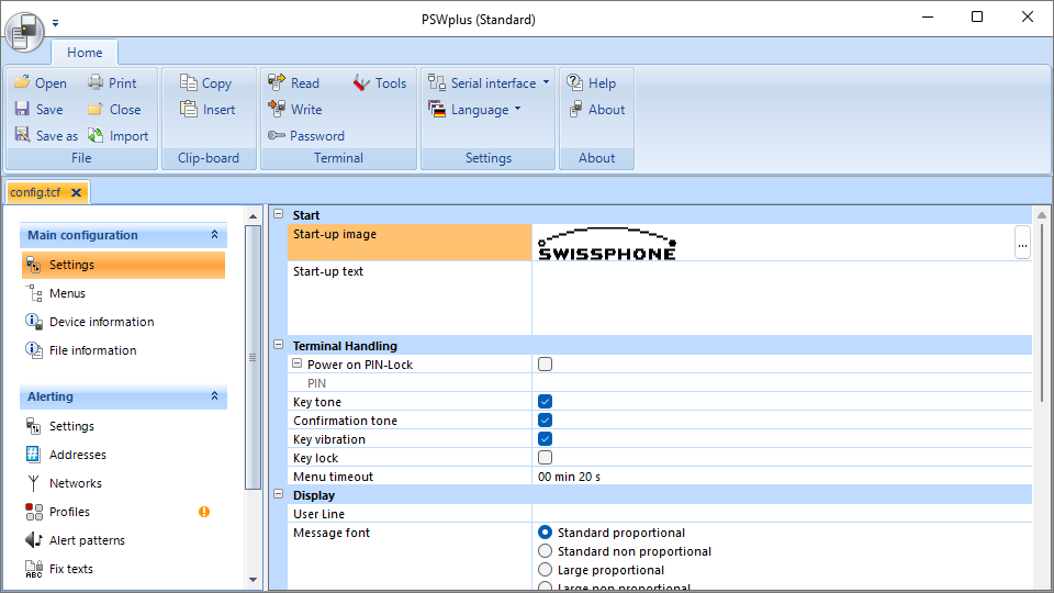
PSWplus is quite simple in principle. You can read a configuration from a pager or write one to it. You can set or reset a programming password, optionally with a hard lock. If a pager is locked with a password, its configuration can only be read if you have the password. Otherwise, it can only be reset to factory defaults. However, if the hard lock is active, even that is not allowed. Configurations can be saved and loaded to and from configuration files which are described in Terminal Configuration Files. There's a little help section, you can choose a serial port or tcp/ip connection and there's a collection of miscellaneous tools.
Normal users will only have access to PSWplus (Standard), but there's also PSWplus (Service) and PSWplus (Crypto) which I don't have access to. Crypto is used to configure message encryption keys. As far as I know, service is only given to authorized service technicians, contracted by Swissphone. It allows you to measure a few low level radio values, change the middle frequency of the pager and a few other little things. You can find a few remnants of the service version in the standard version if you do a little reverse engineering. You can even find a screenshot in Service Anleitung DE10A V1_2_EN, a document on Swissphone's website. Actually, most of what I've learned about the pager comes from reverse engineering PSWplus. I did a combination of decompiling it and sniffing the serial protocol. There is also the programming guide where I learned about PSWplus (Crpyto).
Terminal Configuration Files
PSWplus saves the configuration in .tcf files. TCF stands for Terminal Configuration File. Basically they're an XML file that can optionally be wrapped in a zip file. The zipped variant is what you get if you save a file using the software. However, it can read both variants just fine. If you take a look at such a config file, you'll notice that it's quite self-explanatory as there are lots of useful names in the XML.
Serial Sniffing
The software interfaces with the pager through a serial interface. For this, Swion offers a programming station which you can acquire for around 100 bucks. There's a few different models of programming station, but all they really are, are UART adapters. When I discovered this, I was like: "Wait, I have a USB to UART adapter lying around". Turns out, a simple FT232 is enough.
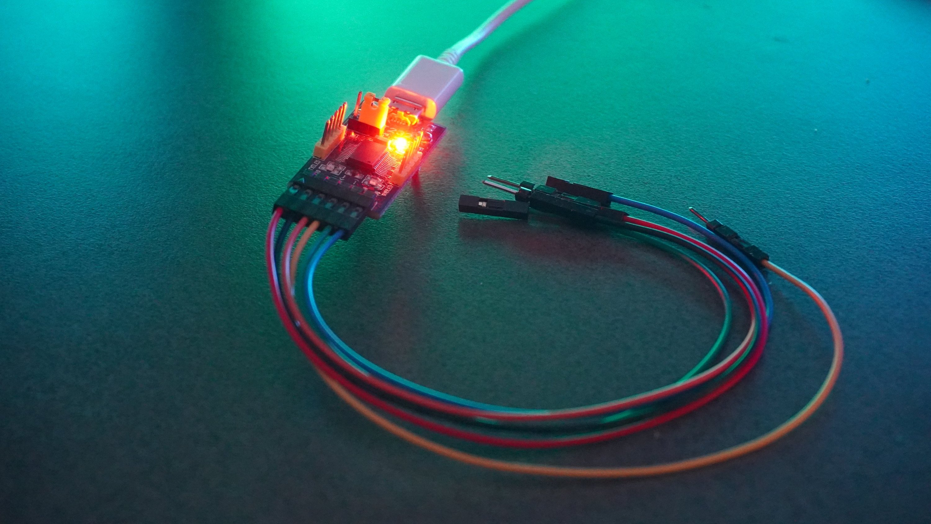
If you do a little research, you'll find the pinout for the DE10A. I found the pinout on W3AXL Wiki. For your convenience, I've made this little pinout image below. The filled pins aren't used for serial communication. RX, TX and GND are enough.
With all that you can easily and cheaply configure such a pager yourself.
When trying to reverse engineer the serial protocol, my first intuition was to sniff the serial connection with something like Wireshark. Unfortunately the only viable option was Serial Port Monitor which was not free. The Free version (which is a completely different product) didn't work for me, so I had to use the advanced version which, at least, had a 14-day free trial. But I got to admit, it's a really solid piece of software and working with it went quite well. In the end, I only used this technique to verify that my understanding of the message format was in fact correct. Most of the knowledge, I gathered was through decompilation.
Decompilation
If you take a look at the installation directory of PSWplus, you'll find a few interesting files as well a lot of boring files. These are the most relevant ones:
- PSWplus.exe the main executable containing all UI code
- Swissphone.ComLibrary.Phoenix.dll a library containing all the business logic, models and "high" level communication protocol. This is the most important part
- Swissphone.ComLibrary.Phoenix.Driver.Serial.dll the serial driver for communication with a pager
- Swissphone.ComLibrary.Phoenix.Driver.Tcp.dll the TCPIP driver for communication with a pager (newer models support that)
- Swissphone.Log.Log4Net.dll logging backed, not that interesting
- Swissphone.Log.Slf4Net.dll different logging backend, also not that interesting
PSWplus is developed in C# using dotnet runtime 4.7.1 (which is completely outdated) and obfuscated using dotfuscator. So it was quite easy to deobfuscate the relevant binaries using de4dotEx. You just run it on the relevant DLLs and the EXE and tell it to deobfuscate the strings, and you're done. Now you have the deobfuscated version of the binaries.
Using dnSpyEx I could see source code that was presumably quite close to the original. Using this, I was slowly able to find out, how communication worked and what command codes meant what. All in all, I think the code is solid. There are a few design decisions, I don't quite understand and a bit of spaghetti code. But all in all it's reasonable. There's a class for almost every command. Sometimes, similar commands are packed into the same class with a flag differentiating between them. Then there are classes for tasks, which perform certain actions involving an arbitrary amount of commands and sub-tasks as well as additional logic, like resetting a pager to factory defaults.
There is a central task class that seems to be a bit more on the spaghetti side with tasks referencing it and itself referencing other tasks. There's multiple different serial protocols, each having their own handler class for serialization and deserialization. Each command specifies which serial protocol it uses. To me, it seems like there's one main protocol which is similar to PPP/HDLC. All communication, I've observed has been through this protocol, except for the initial connection establishment, which uses the raw serial connection.
Serial protocols
public enum ProtocolType
{
  Serial,         // Raw serial
  SciFrame,       // Main protocol
  UpdateFrame,    // Perhaps used with the update command?
  XModemTransmit, // Used for communication in a special mode?
  XModemReceive,  // Same as above
  None
}
SCI frame protocol
As I said before, the main serial protocol, called SCI sends frames with HDLC frame markers and a CRC-8 DallaxMaxim checksum. The configuration for the checksum looks like this:
width: 8,
poly: 0x31,
init: 0xff,
refin: true,
refout: true,
xorout: 0x00,
check: 0x00,
residue: 0x00,
All data between the frame markers is escaped. This includes the checksum itself. Escaping works by replacing all bytes that are either 0x7E or 0x7D with 0x7D and the original byte XORed with 0x20. This is the same as HDLC does it. So 0x7E will result in 0x7D5E and 0x7D will result in 0x7D5D.
Frame:
0x7E [escaped payload] [escaped CRC-8 checksum] 0x7E

Payload:
[command type byte] 0x03 [command sub type byte] [args]
All commands seem to be categorized based on their command type by what they do. Here are the most important ones:
- 0x00: System commands for reading information etc.
- 0x01: Devices boot/reboot commands
- 0x14: Storage commands
- 0x43: Feature flag commands
- 0x67: Lock commands
The sub-type determines the actual command in each category. There's a 0x03 in between the command type and command sub-type. I've started to reference commands by their combined command type and command sub-type. So 0x0001 would be what I call SysReadFirmwareVersion with command type 0x00 and sub-type 0x01.
I found a few commands, that don't seem to be used by PSWplus (Standard). One very interesting one is 0x0007, which I call "SysWriteFeatureFlags". It allows you to set the feature flags to a certain value. Feature flags are a 32 bit bitmask. You can read them using the command 0x0006 - "SysReadFeatureFlags". I discovered these by just trying out IDs, which were missing in between the known ones. If a command ID is valid, the pager will respond, even if you sent invalid arguments. However, if the command ID is not valid, it will not respond at all. That way, you can try out IDs until you find one that the pager responds to. Now you just have to guess the arguments and what it does.
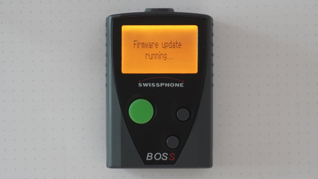
Another one is 0x0004 which I call SysStartFirmwareUpdate it's used without any arguments and puts the pager into a mode where it seemingly accepts a firmware update package and displays "Firmware update running...".
Update frame protocol
There's also an "UpdateFrame" protocol. However, it seems to be unused in PSWplus (Standard). The name leads me to believe that it's used to transmit firmware updates to the pager, but I cannot confirm that at this point.
[unknown byte] [length byte] [payload bytes] [checksum byte]I think there's a one-second timeout. Unfortunately, I don't know anything else about this protocol.
Hardware
To break things up, I'll give you a quick rundown of the Hardware.


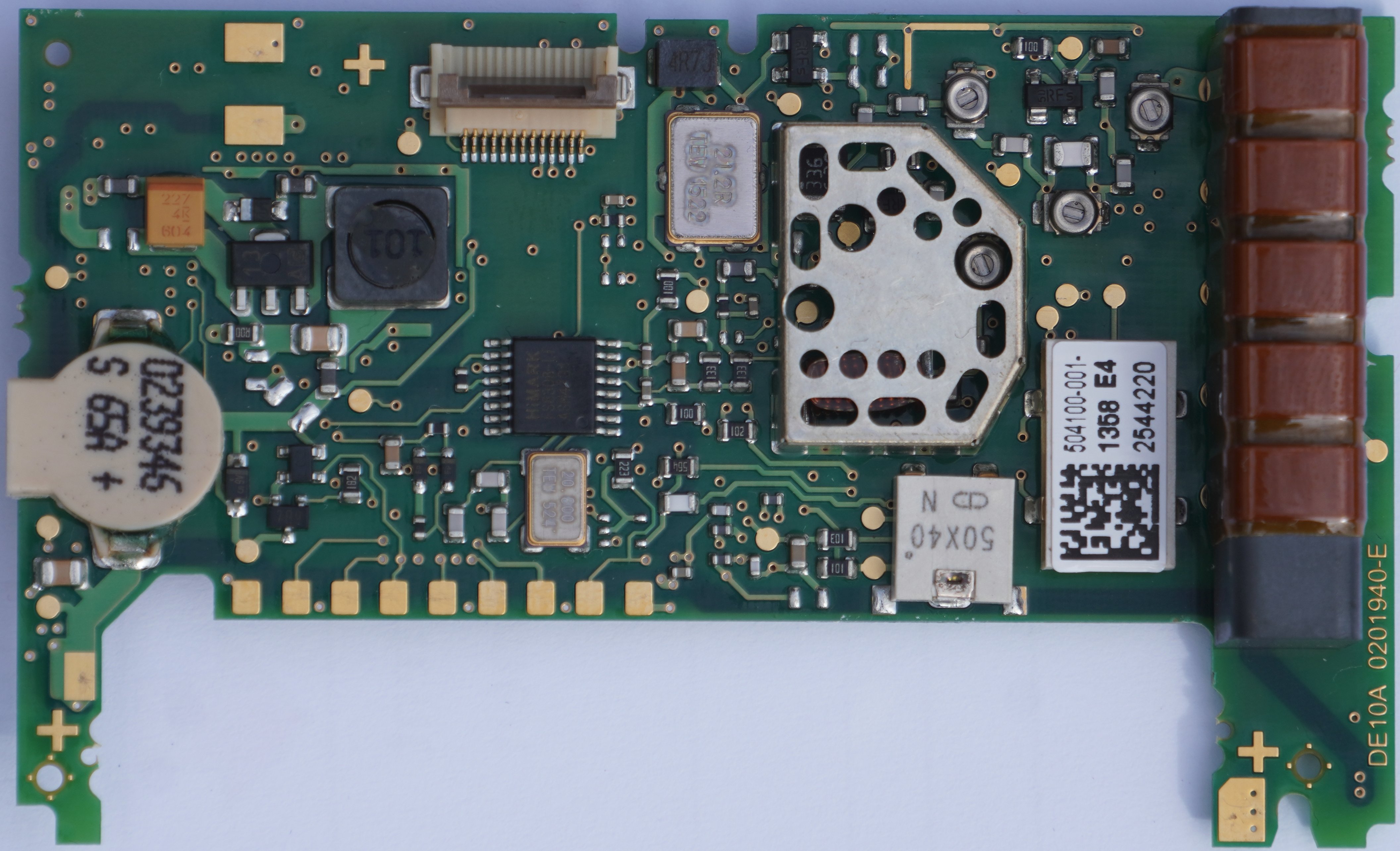
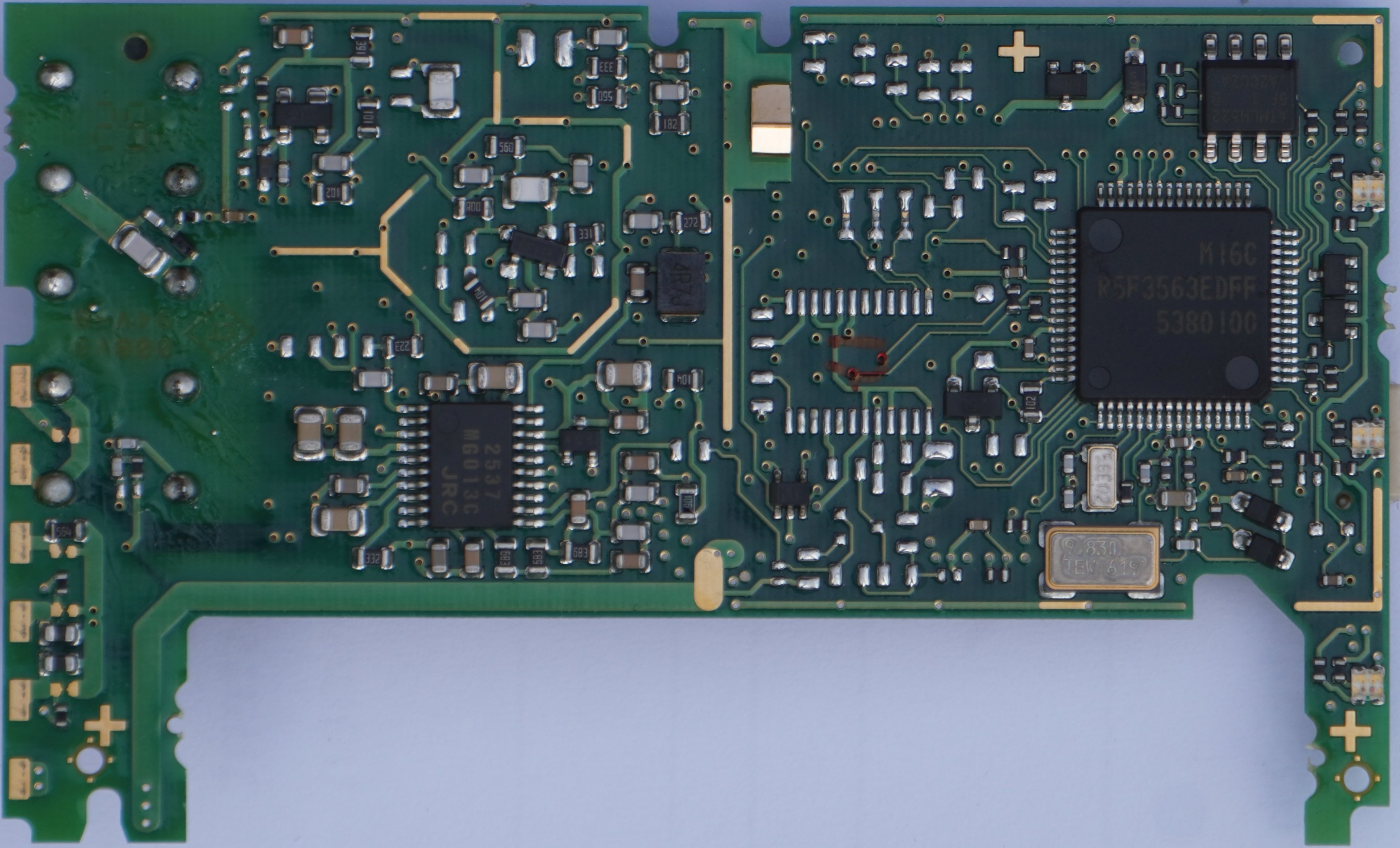
Unmarked images for top and bottom
As you can see, I was able to identify most of the test points. This was because while searching for "Swissphone DE10A" online, I was greeted with a link to this: Service Anleitung DE10A V1_2_EN. It's a very interesting read, but I'm not sure if this document is supposed to be publicly available…
However, there's also a lot, we can find out from just looking at the hardware at hand. I was able to identify all microchips on the board. These are:
- A Renesas M16C R5F3563EDFF
- Main micro controller
- Renesas M16C 56D Group
- 256K ROM
- 20K RAM
- An NJM2537 low power FM IC
- An AT25512 EEPROM
- A HiMark FS8308 Frequency Synthesizer
On the top side of the board, there are nine pads that make up a "Flash Programmer Interface" as Swissphone calls it in their service manual. I'm quite sure that it can be used to communicate with the MCU for debugging and flashing of firmware. The MCU has a special mode for that, which is documented by the manufacturer. However, I was not able to establish communication to it. Unfortunately, the docs aren't helpful in this case and I'm also not 100% certain about the function of each pad. It could be that Swissphone deactivated the interface, but given what I've seen, I think that's unlikely. The way these pins are exposed make it seem like, Swispshone have a matching connector, they can use without removing the board from the case.
Firmware
Firmware version codes seem to have the following format:
[Major.Minor] FRU[2|5]Mtev

2 is for BOSS 915
5 is for BOSS 935
These are the firmware versions, I know of:
| Version | Build ID | Model | Date & Time |
|---|---|---|---|
| 3.94 FRU2Mtev | 20140128T0914 27253 544901 | BOSS 915 | 2014-01-28 09:14 |
| 4.22 FRU2Mtev | 20150720T0932 31191 544901 | BOSS 915 | 2015-07-20 09:32 |
| 4.42 FRU2Mtev | 20160414T1343 33245 544901 | BOSS 915 | 2016-04-14 13:43 |
| 4.90 FRU5Mtev | 20170601T1359 35594 544900 | BOSS 935 | 2017-06-01 13:59 |
| 6.24 FRU2Mtev | 20210429T1104 e0ee768b 544901 | BOSS 915 | 2021-04-29 11:04 |
As you can see, there's a date and time in the build ID that I've put into the table separately as well. The model can be deduced from the version string, as described above. It also seems to be part of the build ID (last three digits: 901 for 915 and 900 for 935).
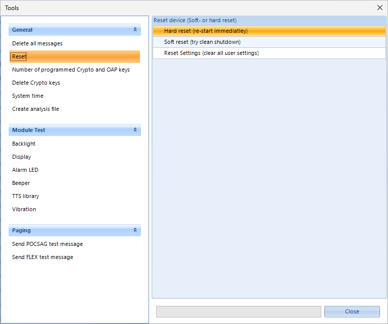
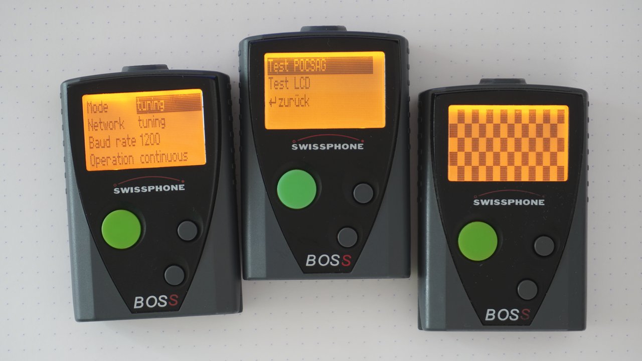
The firmware supports different operating modes. Obviously, there's the normal operation mode in which the pager does its usual dues.
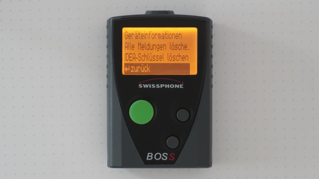
There's also a hidden menu mode, which you can activate by pressing all buttons while inserting the battery, or via the reset command. It allows you to view the pagers firmware information and serial number, delete crypto keys, and delete all messages.
Finally, the pager can boot into test mode. This can be done by holding the two navigation buttons while inserting the battery, or via the reset command. Here, you can test the display as well as a lot of radio related functions.
Unfortunately, I don't know much more about the firmware itself, as I don't have access to the binary or any update packages. Time will tell, if I'm going to be able to dump the firmware from a pager.
Storage Blocks
The firmware stores its configuration data etc. on the EEPROM in logical storage blocks. These have an ID, a length, a version, and permission flags. There are commands to read and write them. You can also get a directory of storage blocks and their metadata, which looks a bit like this:
| ID | Version | Size | Flags |
|---|---|---|---|
| 641d | 0 | 6 | R--- |
| 641e | 0 | 6 | R--- |
| 641f | 0 | 6 | R--- |
| 8410 | 0 | 1 | RW-- |
| e000 | 0 | 25 | RW-P |
| e100 | 1 | 27 | R--P |
| e101 | 0 | 64 | RW-P |
| e301 | 1 | 29 | RWIP |
| f000 | 1 | 3040 | RW-- |
| ... | ... | ... | ... |
The permission flags are labeled with R, W, I and P. I guess R means read and W means write. I don't know what I and P mean. Most of these blocks have their own class in PSWplus (Standard), so you can mostly just search for the block ID in dnSpy and find the class that defines the structure. Because there's an XML path for each field, it's quite easy to see what the blocks are for. There can be different versions of each block, depending on the firmware version and model of the pager with different structures. There's a class for each version.
Here are a few blocks interesting blocks, I've discovered:
| ID(s) | Description | Flags |
|---|---|---|
| 1100 - 113f | Profiles 1 - 64 | RWIP |
| 1800 - 187f | Fixtexts 1 - 128 | RWIP |
| 2C01 | Battery config | RWIP |
| 3221 | OAP password | RWIP |
| 3850 | Username | RWIP |
| 4000 | Received messages | RW-- |
| 4200 | Various radio settings | RWIP |
| 4400 | Pocsag decoder settings | RWIP |
| 4500 | PLL tuning, clocks, frequncy | RWIP |
| 4600 | Temperature compensation | RWIP |
| 4800 - 4807 | Network config 1 - 8 | RWIP |
| 5000 - 501f | IDEA Message Keys 1 - 32, write only | -W-P |
| 5100 | IDEA OAP Key, write only | -W-P |
| 5200 | Crypto ORG code, plaintext identifier | RWIP |
| 5300 - 531f | Unknown, perhaps some keys (could be AES+) | -W-P |
| 5400 | Crypto pair toggles, not accessible | RWIP |
| 8410 | Pagerlock mode? | RW-- |
| E050 | Unknown, not accessible | ---- |
| E100 | Auth, programming password | R--P |
| E101 | Some string with PSW version | RW-P |
| E110 | Unknown, not accessible | ---- |
| E300 | Serialnumber, not accessible | ---- |
| E301 | pager id and organisation id | RWIP |
I'm sure there are loads more, but these are the ones I've stumbled upon and cared to investigate. The blocks for message keys were a fun story. I wanted to know how keys are programmed, but without access to PSWplus (Crypto), I couldn't just look at that to find it out. Instead, I sniffed the serial connection while the OAP key was written and found that it was written to block 5100. Interestingly, there were 32 blocks with 16 bytes length, that were write only next to it. That was suspicious to me, so I just wrote some random data to one of those blocks, asked the pager how many keys were programmed, and as I expected, it was one.
Outlook and closing thoughts
This was a passion project because I think the technology is just very neat. It was just my curiosity running wild, so I never had the intent to make any money with it. In fact, I've spent a considerable amount of time and money on it. So please keep in mind, all of what I'm saying here should be taken with a grain of salt. This was not endorsed by Swissphone, and I'm not connected to them or their partners in any way. In my research, I only used tools, documents, and knowledge that is freely available on the internet.
There still are a few things, one could try to do. Reading out the EEPROM should be relatively easy to do, as the docs describe pins and the SPI protocol quite well. There's also the "Flash Programmer Interface", which I couldn't get to work. Looking at the firmware would be very interesting as well, but I was unable to get my hands on an update package.
However, I'd like to stop here, because I've spent more than enough time on it. Perhaps someone is interested in picking it up and doing more research.
More from the pagerverse
This article was in development for quite a long time, so I'm glad it's released now. I did a lot of research. Much more than I could ever hope to write about. But there are a few more articles on the topic, you might want to read.
- 📌 The DE10A pager
- The BOSS pager exploit
- 🔜 A cool startup image for the BOSS pager
- 🔜 The Swion Terminal Dump